6.1.2. Input Files
The user configures the aerodynamic model parameters via a primary AeroDyn input file, as well as separate input files for airfoil and blade data. When used in standalone mode, an additional driver input file is required. This driver file specifies initialization inputs normally provided to AeroDyn by OpenFAST, as well as the per-time-step inputs to AeroDyn.
As an example, the driver.dvr file is the main driver, the input.dat is the primary input file, the blade.dat file contains the blade
geometry data, and the airfoil.dat file contains the airfoil
angle of attack, lift, drag, moment coefficients, and pressure
coefficients. Example input files are included in Section 6.1.5.
No lines should be added or removed from the input files, except in tables where the number of rows is specified and comment lines in the AeroDyn airfoil data files.
6.1.2.1. Units
AeroDyn uses the SI system (kg, m, s, N). Angles are assumed to be in radians unless otherwise specified.
6.1.2.2. AeroDyn Driver Input File
The driver input file is only needed for the standalone version of AeroDyn and contains inputs normally generated by OpenFAST, and necessary to control the aerodynamic simulation for uncoupled models. A sample AeroDyn driver input file is given in Section 6.1.5.
Set the Echo flag in this file to TRUE if you wish to have the
AeroDyn_Driver executeable echo the contents of the driver input file (useful
for debugging errors in the driver file). The echo file has the naming
convention of OutFileRoot**.ech, where OutFileRoot is
specified in the I/O SETTINGS section of the driver input file below.
AD_InputFile is the filename of the primary AeroDyn input file.
This name should be in quotations and can contain an absolute path or a
relative path.
The TURBINE DATA section defines the AeroDyn-required turbine geometry
for a rigid turbine, see Figure 1. NumBlades specifies the number
of blades; only one-, two-, or three-bladed rotors are permitted.
HubRad specifies the radius to the blade root from the
center-of-rotation along the (possibly preconed) blade-pitch axis;
HubRad must be greater than zero. HubHt specifies the
elevation of the hub center above the ground (or above the mean sea
level (MSL) for offshore wind turbines or above the seabed for MHK
turbines). Overhang specifies the distance along the (possibly
tilted) rotor shaft between the tower centerline and hub center;
Overhang is positive downwind, so use a negative number for upwind
rotors. ShftTilt is the angle (in degrees) between the rotor shaft
and the horizontal plane. Positive ShftTilt means that the
downwind end of the shaft is the highest; upwind turbines have negative
ShftTilt for improved tower clearance. Precone is the angle
(in degrees) between a flat rotor disk and the cone swept by the blades,
positive downwind; upwind turbines have negative Precone for
improved tower clearance.
The I/O SETTINGS section controls the creation of the results file. If
OutFileRoot is specified, the results file will have the filename
OutFileRoot**.#.out*, where the ‘#’ character is an integer
number corresponding to a test case line found in the COMBINED-CASE
ANALYSIS section described below. If an empty string is provided for
OutFileRoot, then the driver file’s root name will be used
instead. If TabDel is TRUE, a TAB character is used between
columns in the output file; if FALSE, fixed-width is used otherwise.
OutFmt is any valid Fortran numeric format string, which is used
for text output, excluding the time channel. The resulting field should
be 10 characters, but AeroDyn does not check OutFmt for validity.
If you want a sound generated on program exit, set Beep to true.
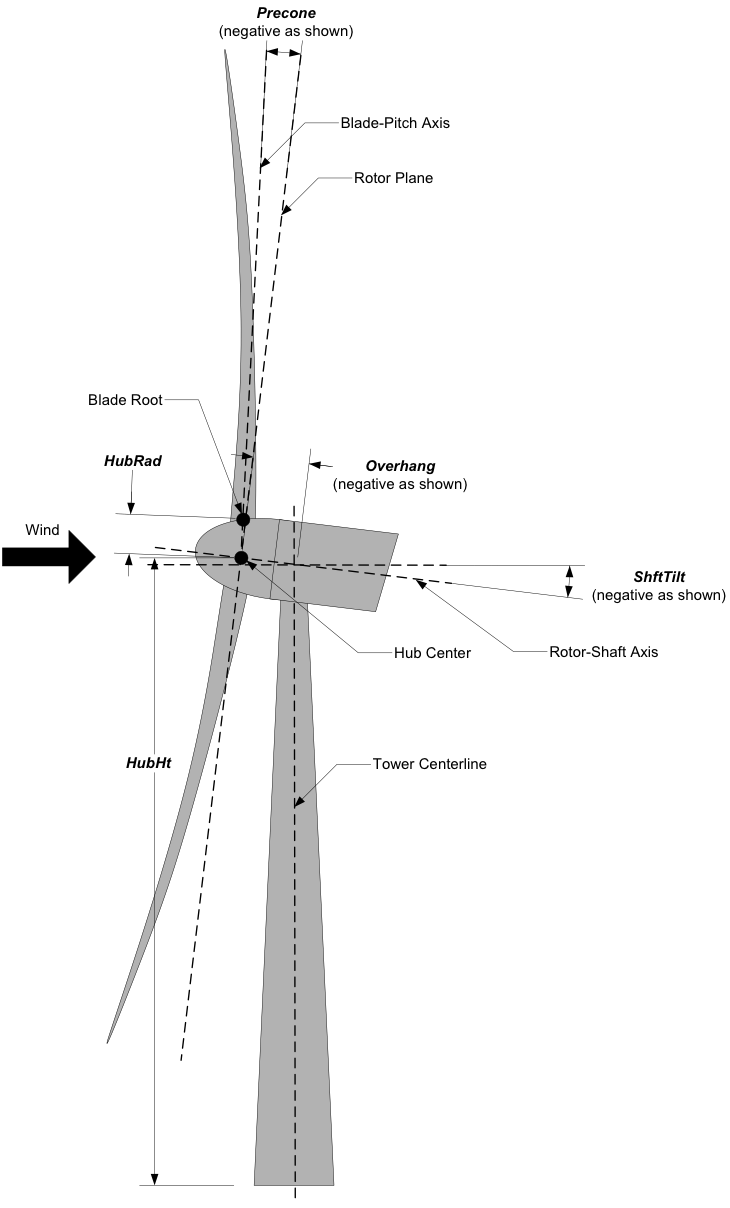
Fig. 6.1 AeroDyn Driver Turbine Geometry
The COMBINED-CASE ANALYSIS section allows you to execute NumCases
number of simulations for the given TURBINE DATA with a single driver
input file. There will be one row in the subsequent table for each of
the NumCases specified (plus two table header lines). The
information within each row of the table fully specifies each
simulation. Each row contains the following columns: WndSpeed,
ShearExp, RotSpd, Pitch, Yaw, dT, and
Tmax. The local undisturbed wind speed for any given blade or
tower node is determined using,
where \(\mathrm{WndSpeed}\) is the steady wind speed (fluid flow speed in the
case of an MHK turbine) located at elevation \(\mathrm{HubHt}\), \(Z\) is the
instantaneous elevation of the blade or tower node above the ground (or
above the MSL for offshore wind turbines or above the seabed for MHK
turbines), and \(\mathrm{ShearExp}\) is the power-law shear exponent. The fixed
rotor speed (in rpm) is given by RotSpd (positive clockwise
looking downwind), the fixed blade-pitch angle (in degrees) is given by
Pitch (positive to feather, leading edge upwind), and the fixed
nacelle-yaw angle (in degrees) is given by Yaw (positive rotation
of the nacelle about the vertical tower axis, counterclockwise when
looking downward). While the flow speed and direction in the AeroDyn
driver is uniform and fixed (depending only on elevation above ground),
Yaw and ShftTilt (from the TURBINE DATA section above) can
introduce skewed flow. dT is the simulation time step, which must
match the time step for the aerodynamic calculations (DTAero) as
specified in the primary AeroDyn input file, and Tmax is the total
simulation time.
6.1.2.3. AeroDyn Primary Input File
The primary AeroDyn input file defines modeling options, environmental conditions (except freestream flow), airfoils, tower nodal discretization and properties, as well as output file specifications.
The file is organized into several functional sections. Each section corresponds to an aspect of the aerodynamics model. A sample AeroDyn primary input file is given in Section 6.1.5.
The input file begins with two lines of header information which is for your use, but is not used by the software.
6.1.2.3.1. General Options
Set the Echo flag to TRUE if you wish to have AeroDyn echo the
contents of the AeroDyn primary, airfoil, and blade input files (useful
for debugging errors in the input files). The echo file has the naming
convention of OutRootFile**.AD.ech*. ``OutRootFile is either
specified in the I/O SETTINGS section of the driver input file when
running AeroDyn standalone, or by the OpenFAST program when running a
coupled simulation.
DTAero sets the time step for the aerodynamic calculations. For
accuracy and numerical stability, we recommend that DTAero be set
such that there are at least 200 azimuth steps per rotor revolution.
However, when AeroDyn is coupled to OpenFAST, OpenFAST may require time steps
much smaller than this rule of thumb. If UA is enabled while using very
small time steps, you may need to recompile AeroDyn in double precision
to avoid numerical problems in the UA routines. The keyword DEFAULT
for DTAero may be used to indicate that AeroDyn should employ the
time step prescribed by the driver code (FAST or the standalone driver
program).
Set WakeMod to 0 if you want to disable rotor wake/induction
effects or 1 to include these effects using the BEM theory model. Set
AFAeroMod to 1 to include steady blade airfoil aerodynamics or 2
to enable UA; AFAeroMod must be 1 during linearization analyses
with AeroDyn coupled to OpenFAST. Set TwrPotent to 0 to disable the
potential-flow influence of the tower on the fluid flow local to the
blade, 1 to enable the standard potential-flow model, or 2 to include
the Bak correction in the potential-flow model. Set the TwrShadow
flag to TRUE to include the influence of the tower on the flow local to
the blade based on the downstream tower shadow model or FALSE to disable
these effects. If the tower influence from potential flow and tower
shadow are both enabled, the two influences will be superimposed. Set
the TwrAero flag to TRUE to calculate fluid drag loads on the
tower or FALSE to disable these effects. During linearization analyses
with AeroDyn coupled OpenFAST and BEM enabled (WakeMod = 1), set the
FrozenWake flag to TRUE to employ frozen-wake assumptions during
linearization (i.e. to fix the axial and tangential induces velocities,
and , at their operating-point values during linearization) or FALSE to
recalculate the induction during linearization using BEM theory. Set the
CavitCheck flag to TRUE to perform a cavitation check for MHK
turbines or FALSE to disable this calculation. If CavitCheck is
TRUE, AFAeroMod must be set to 1 because the cavitation check does
not function with unsteady airfoil aerodynamics.
6.1.2.3.2. Environmental Conditions
AirDens specifies the fluid density and must be a value greater
than zero; a typical value is around 1.225 kg/m3 for air (wind
turbines) and 1025 kg/m3 for seawater (MHK turbines).
KinVisc specifies the kinematic viscosity of the air (used in the
Reynolds number calculation); a typical value is around 1.460E-5
m2/s for air (wind turbines) and 1.004E-6 m2/s for
seawater (MHK turbines). SpdSound is the speed of sound in air
(used to calculate the Mach number within the unsteady airfoil
aerodynamics calculations); a typical value is around 340.3 m/s. The
last three parameters in this section are only used when
CavitCheck = TRUE for MHK turbines. Patm is the atmospheric
pressure above the free surface; typically around 101,325 Pa. Pvap
is the vapor pressure of the fluid; for seawater this is typically
around 2,000 Pa. FluidDepth is the distance from the hub center to
the free surface.
6.1.2.3.3. Blade-Element/Momentum Theory
The input parameters in this section are only used when WakeMod =
1.
SkewMod determines the skewed-wake correction model. Set
SkewMod to 1 to use the uncoupled BEM solution technique without
an additional skewed-wake correction. Set SkewMod to 2 to include
the Pitt/Peters correction model. The coupled model ``SkewMod=
3`` is not available in this version of AeroDyn.
Set TipLoss to TRUE to include the Prandtl tip-loss model or FALSE
to disable it. Likewise, set HubLoss to TRUE to include the
Prandtl hub-loss model or FALSE to disable it.
Set TanInd to TRUE to include tangential induction (from the
angular momentum balance) in the BEM solution or FALSE to neglect it.
Set AIDrag to TRUE to include drag in the axial-induction
calculation or FALSE to neglect it. If TanInd = TRUE, set
TIDrag to TRUE to include drag in the tangential-induction
calculation or FALSE to neglect it. Even when drag is not used in the
BEM iteration, drag is still used to calculate the nodal loads once the
induction has been found,
IndToler sets the convergence threshold for the iterative
nonlinear solve of the BEM solution. The nonlinear solve is in terms of
the inflow angle, but IndToler represents the tolerance of the
nondimensional residual equation, with no physical association possible.
When the keyword DEFAULT is used in place of a numerical value,
IndToler will be set to 5E-5 when AeroDyn is compiled in single
precision and to 5E-10 when AeroDyn is compiled in double precision; we
recommend using these defaults. MaxIter determines the maximum
number of iterations steps in the BEM solve. If the residual value of
the BEM solve is not less than or equal to IndToler in
MaxIter, AeroDyn will exit the BEM solver and return an error
message.
6.1.2.3.4. Unsteady Airfoil Aerodynamics Options
The input parameters in this section are only used when AFAeroMod
= 2.
UAMod determines the UA model. Setting UAMod to 1 enables
original theoretical developments of B-L, 2 enables the extensions to
B-L developed by González, and 3 enables the extensions to B-L developed
by Minnema/Pierce. While all of the UA models are documented in this
manual, the original B-L model is not yet functional. Testing has shown
that the González and Minnema/Pierce models produce reasonable
hysteresis of the normal force, tangential force, and pitching-moment
coefficients if the UA model parameters are set appropriately for a
given airfoil, Reynolds number, and/or Mach number. However, the
results will differ a bit from earlier versions of AeroDyn, (which was
based on the Minnema/Pierce extensions to B-L) even if the default UA
model parameters are used, due to differences in the UA model logic
between the versions. We recommend that users run test cases with
uniform inflow and fixed yaw error (e.g., through the standalone AeroDyn
driver) to examine the accuracy of the normal force, tangential force,
and pitching-moment coefficient hysteresis and to adjust the UA model
parameters appropriately.
FLookup determines how the nondimensional separation distance
value, f’, will be calculated. When FLookup is set to TRUE, f’
is determined via a lookup into the static lift-force coefficient and
drag-force coefficient data. Using best-fit exponential equations
(``FLookup = FALSE``) is not yet available, so ``FLookup`` must be
``TRUE`` in this version of AeroDyn.
6.1.2.3.5. Airfoil Information
This section defines the airfoil data input file information. The airfoil data input files themselves (one for each airfoil) include tables containing coefficients of lift force, drag force, and optionally pitching moment, and minimum pressure versus AoA, as well as UA model parameters, and are described in Section 6.1.2.3.9.
The first 5 lines in the AIRFOIL INFORMATION section relate to the
format of the tables of static airfoil coefficients within each of the
airfoil input files. InCol_Alfa, InCol_Cl,
InCol_Cd, InCol_Cm, and InCol_Cpmin are column
numbers in the tables containing the AoA, lift-force coefficient,
drag-force coefficient, pitching-moment coefficient, and minimum
pressure coefficient, respectively (normally these are 1, 2, 3, 4, and
5, respectively). If pitching-moment terms are neglected with
UseBlCm = FALSE, InCol_Cm may be set to zero, and if the
cavitation check is disabled with CavitCheck = FALSE,
InCol_Cpmin may be set to zero.
Specify the number of airfoil data input files to be used using
NumAFfiles, followed by NumAFfiles lines of filenames. The
file names should be in quotations and can contain an absolute path or a
relative path e.g., “C:\airfoils\S809_CLN_298.dat” or
“airfoils\S809_CLN_298.dat”. If you use relative paths, it is
relative to the location of the current working directory. The blade
data input files will reference these airfoil data using their line
identifier, where the first airfoil file is numbered 1 and the last
airfoil file is numbered NumAFfiles.
6.1.2.3.6. Rotor/Blade Properties
Set UseBlCm to TRUE to include pitching-moment terms in the blade
airfoil aerodynamics or FALSE to neglect them; if UseBlCm = TRUE,
pitching-moment coefficient data must be included in the airfoil data
tables with InCol_Cm not equal to zero.
The blade nodal discretization, geometry, twist, chord, and airfoil
identifier are set in separate input files for each blade, described in
Section 6.1.2.3.10. ADBlFile(1) is the filename for blade 1,
ADBlFile(2) is the filename for blade 2, and ADBlFile(3) is
the filename for blade 3, respectively; the latter is not used for
two-bladed rotors and the latter two are not used for one-bladed rotors.
The file names should be in quotations and can contain an absolute path
or a relative path. The data in each file need not be identical, which
permits modeling of aerodynamic imbalances.
6.1.2.3.7. Tower Influence and Aerodynamics
The input parameters in this section pertain to the tower influence
and/or tower drag calculations and are only used when TwrPotent >
0, TwrShadow = TRUE, or TwrAero = TRUE.
NumTwrNds is the user-specified number of tower analysis nodes and
determines the number of rows in the subsequent table (after two table
header lines). NumTwrNds must be greater than or equal to two; the
higher the number, the finer the resolution and longer the computational
time; we recommend that NumTwrNds be between 10 and 20 to balance
accuracy with computational expense. For each node, TwrElev
specifies the local elevation of the tower node above ground (or above
MSL for offshore wind turbines or above the seabed for MHK turbines),
TwrDiam specifies the local tower diameter, and TwrCd
specifies the local tower drag-force coefficient. TwrElev must be
entered in monotonically increasing order—from the lowest (tower-base)
to the highest (tower-top) elevation. See Figure 2.
6.1.2.3.8. Outputs
Specifying SumPrint to TRUE causes AeroDyn to generate a summary
file with name OutFileRoot**.AD.sum*. ``OutFileRoot is either
specified in the I/O SETTINGS section of the driver input file when
running AeroDyn standalone, or by the OpenFAST program when running a
coupled simulation. See section 5.2 for summary file details.
AeroDyn can output aerodynamic and kinematic quantities at up to nine
nodes along the tower and up to nine nodes along each blade.
NBlOuts specifies the number of blade nodes that output is
requested for (0 to 9) and BlOutNd on the next line is a list
NBlOuts long of node numbers between 1 and NumBlNds
(corresponding to a row number in the blade analysis node table in the
blade data input files), separated by any combination of commas,
semicolons, spaces, and/or tabs. All blades have the same output node
numbers. NTwOuts specifies the number of tower nodes that output
is requested for (0 to 9) and TwOutNd on the next line is a list
NTwOuts long of node numbers between 1 and NumTwrNds
(corresponding to a row number in the tower analysis node table above),
separated by any combination of commas, semicolons, spaces, and/or tabs.
The outputs specified in the OutList section determine which
quantities are actually output at these nodes.
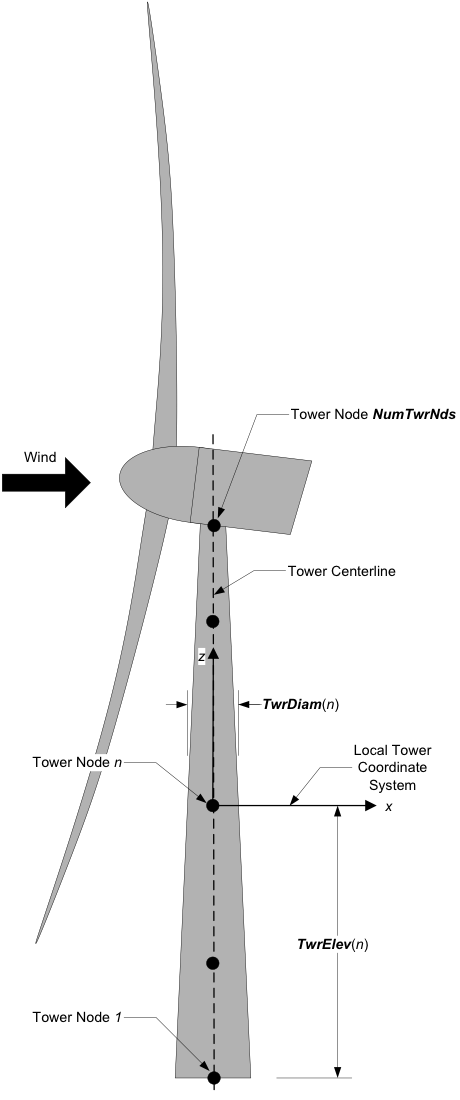
Fig. 6.2 AeroDyn Tower Geometry
The OutList section controls output quantities generated by
AeroDyn. Enter one or more lines containing quoted strings that in turn
contain one or more output parameter names. Separate output parameter
names by any combination of commas, semicolons, spaces, and/or tabs. If
you prefix a parameter name with a minus sign, “-”, underscore, “_”, or
the characters “m” or “M”, AeroDyn will multiply the value for that
channel by –1 before writing the data. The parameters are written in the
order they are listed in the input file. AeroDyn allows you to use
multiple lines so that you can break your list into meaningful groups
and so the lines can be shorter. You may enter comments after the
closing quote on any of the lines. Entering a line with the string “END”
at the beginning of the line or at the beginning of a quoted string
found at the beginning of the line will cause AeroDyn to quit scanning
for more lines of channel names. Blade and tower node-related quantities
are generated for the requested nodes identified through the
BlOutNd and TwOutNd lists above. If AeroDyn encounters an
unknown/invalid channel name, it warns the users but will remove the
suspect channel from the output file. Please refer to Appendix E for a
complete list of possible output parameters.
6.1.2.3.9. Airfoil Data Input File
The airfoil data input files themselves (one for each airfoil) include tables containing coefficients of lift force, drag force, and pitching moment versus AoA, as well as UA model parameters. In these files, any line whose first non-blank character is an exclamation point (!) is ignored (for inserting comment lines). The non-comment lines should appear within the file in order, but comment lines may be intermixed as desired for reading clarity. A sample airfoil data input file is given Section 6.1.5.
InterpOrd is the order the static airfoil data is interpolated
when AeroDyn uses table look-up to find the lift-, drag-, and optional
pitching-moment, and minimum pressure coefficients as a function of AoA.
When InterpOrd is 1, linear interpolation is used; when
InterpOrd is 3, the data will be interpolated with cubic splines;
if the keyword DEFAULT is entered in place of a numerical value,
InterpOrd is set to 3.
NonDimArea is the nondimensional airfoil area (normalized by the
local BlChord squared), but is currently unused by AeroDyn.
NumCoords is the number of points to define the exterior shape of
the airfoil, plus one point to define the aerodynamic center, and
determines the number of rows in the subsequent table; NumCoords
must be exactly zero or greater than or equal to three. For each point,
the nondimensional X and Y coordinates are specified in the table,
X_Coord and Y_Coord (normalized by the local
BlChord). The first point must always locate the aerodynamic
center (reference point for the airfoil lift and drag forces, likely not
on the surface of the airfoil); the remaining points should define the
exterior shape of the airfoil. The airfoil shape is currently unused by
AeroDyn, but when AeroDyn is coupled to OpenFAST, the airfoil shape will be
used by OpenFAST for blade surface visualization when enabled.
Specify the number of Reynolds number- or aerodynamic-control
setting-dependent tables of data for the given airfoil via the
NumTabs setting. Currently, AeroDyn can only use the first table
in any given airfoil file, so you should set ``NumTabs = 1`` and you
will need to make separate airfoil data input files and run separate
simulations if you need to analyze data for different Reynolds numbers
or aerodynamic-control settings. The remaining parameters in the
airfoil data input files are entered separately for each table.
Re and Ctrl are the Reynolds number (in millions) and
aerodynamic-control setting for the included table, but are both
currently unused by AeroDyn.
Set InclUAdata to TRUE if you are including the 32 UA model
parameters (required when AFAeroMod = 2 in the AeroDyn primary
input file):
alpha0specifies the zero-lift AoA (in degrees);alpha1specifies the AoA (in degrees) larger thanalpha0for which f equals 0.7; approximately the positive stall angle;alpha2specifies the AoA (in degrees) less thanalpha0for which f equals 0.7; approximately the negative stall angle;eta_eis the recovery factor and typically has a value in the range [0.85 to 0.95] forUAMod = 1; if the keywordDEFAULTis entered in place of a numerical value,eta_eis set to 0.9 forUAMod = 1, buteta_eis set to 1.0 for otherUAModvalues and wheneverFLookup = TRUE;C_nalphais the slope of the 2D normal force coefficient curve in the linear region;T_f0is the initial value of the time constant associated with Df in the expressions of Df and f’; if the keywordDEFAULTis entered in place of a numerical value,T_f0is set to 3.0;T_V0is the initial value of the time constant associated with the vortex lift decay process, used in the expression ofCvn; it depends on Reynolds number, Mach number, and airfoil; if the keywordDEFAULTis entered in place of a numerical value,T_V0is set to 6.0;T_pis the boundary-layer leading edge pressure gradient time constant in the expression for Dp and should be tuned based on airfoil experimental data; if the keywordDEFAULTis entered in place of a numerical value,T_pis set to 1.7;T_VLis the time constant associated with the vortex advection process, representing the nondimensional time in semi-chords needed for a vortex to travel from the leading to trailing edges, and used in the expression of Cvn; it depends on Reynolds number, Mach number (weakly), and airfoil; valued values are in the range [6 to 13]; if the keywordDEFAULTis entered in place of a numerical value,T_VLis set to 11.0;b1is a constant in the expression of \(\phi_\alpha^c\) and \(\phi_q^c\); this value is relatively insensitive for thin airfoils, but may be different for turbine airfoils; if the keywordDEFAULTis entered in place of a numerical value,b1is set to 0.14, based on experimental results;b2is a constant in the expression of \(\phi_\alpha^c\) and \(\phi_q^c\); this value is relatively insensitive for thin airfoils, but may be different for turbine airfoils; if the keywordDEFAULTis entered in place of a numerical value,b2is set to 0.53, based on experimental results;b5is a constant in the expression of \(K^{'''}_q\), \(Cm_q^{nc}\), and \(K_{m_q}\); if the keywordDEFAULTis entered in place of a numerical value,b5is set to 5, based on experimental results;A1is a constant in the expression \(\phi_\alpha^c\) and \(\phi_q^c\); this value is relatively insensitive for thin airfoils, but may be different for turbine airfoils; if the keywordDEFAULTis entered in place of a numerical value,A1is set to 0.3, based on experimental results;A2is a constant in the expression \(\phi_\alpha^c\) and \(\phi_q^c\); this value is relatively insensitive for thin airfoils, but may be different for turbine airfoils; if the keywordDEFAULTis entered in place of a numerical value,A2is set to 0.7, based on experimental results;A5is a constant in the expression \(K^{'''}_q\), \(Cm_q^{nc}\), and \(K_{m_q}\); if the keywordDEFAULTis entered in place of a numerical value,A5is set to 1, based on experimental results;S1is the constant in the best fit curve of f foralpha0\(\le\) AoA \(\le\)alpha1forUAMod = 1(and is unused otherwise); by definition, it depends on the airfoil;S2is the constant in the best fit curve of f for AoA >alpha1forUAMod = 1(and is unused otherwise); by definition, it depends on the airfoil;S3is the constant in the best fit curve of f foralpha2\(\le\) AoA \(\le\)alpha0forUAMod = 1(and is unused otherwise); by definition, it depends on the airfoil;S4is the constant in the best fit curve of f for AoA <alpha2forUAMod = 1(and is unused otherwise); by definition, it depends on the airfoil;Cn1is the critical value of \(C^{\prime}_n\) at leading-edge separation for positive AoA and should be extracted from airfoil data at a given Reynolds number and Mach number;Cn1can be calculated from the static value of Cn at either the break in the pitching moment or the loss of chord force at the onset of stall;Cn1is close to the condition of maximum lift of the airfoil at low Mach numbers;Cn2is the critical value of \(C^{\prime}_n\) at leading-edge separation for negative AoA and should be extracted from airfoil data at a given Reynolds number and Mach number;Cn2can be calculated from the static value of Cn at either the break in the pitching moment or the loss of chord force at the onset of stall;Cn2is close to the condition of maximum lift of the airfoil at low Mach numbers;St_shis the Strouhal’s shedding frequency; if the keywordDEFAULTis entered in place of a numerical value,St_shis set to 0.19;Cd0is the drag-force coefficient at zero-lift AoA;Cm0is the pitching-moment coefficient about the quarter-chord location at zero-lift AoA, positive for nose up;k0is a constant in the best fit curve of \(\hat{x}_{cp}\) and equals for \(\hat{x}_{AC}-0.25\)UAMod = 1(and is unused otherwise);k1is a constant in the best fit curve of \(\hat{x}_{cp}\) forUAMod = 1(and is unused otherwise);k2is a constant in the best fit curve of \(\hat{x}_{cp}\) forUAMod = 1(and is unused otherwise);k3is a constant in the best fit curve of \(\hat{x}_{cp}\) forUAMod = 1(and is unused otherwise);k1_hatis a constant in the expression of Cc due to leading-edge vortex effects forUAMod = 1(and is unused otherwise);x_cp_baris a constant in the expression of \(\hat{x}_{cp}^{\nu}\) forUAMod = 1(and is unused otherwise); if the keywordDEFAULTis entered in place of a numerical value,x_cp_baris set to 0.2; andUACutOutis the AoA (in degrees) in absolute value above which UA are disabled; if the keywordDEFAULTis entered in place of a numerical value,UACutOutis set to 45.filtCutOffis the cut-off frequency (-3 dB corner frequency) (in Hz) of the low-pass filter applied to the AoA input to UA, as well as to the pitch rate and pitch acceleration derived from AoA within UA; if the keywordDEFAULTis entered in place of a numerical value,filtCutOffis set to 20.
NumAlf is the number of distinct AoA entries and determines the
number of rows in the subsequent table of static airfoil coefficients;
NumAlf must be greater than or equal to one (NumAlf = 1
implies constant coefficients, regardless of the AoA). AeroDyn will
interpolate the data provided via linear interpolation or via cubic
splines, depending on the setting of input InterpOrd above. For
each AoA, you must set the AoA (in degrees), alpha, the lift-force
coefficient, Coefs(:,1), the drag-force coefficient,
Coefs(:,2), and optionally the pitching-moment coefficient,
Coefs(:,3), and minimum pressure coefficient,
Coefs(:,4), but the column order depends on the settings of
InCol_Alfa, InCol_Cl, InCol_Cd, InCol_Cm,
and InCol_Cpmin in the AIRFOIL INFORMATION section of the AeroDyn
primary input file. AoA must be entered in monotonically increasing
order—from lowest to highest AoA—and the first row should be for AoA =
–180 and the last should be for AoA = +180 (unless NumAlf = 1, in
which case AoA is unused). If pitching-moment terms are neglected with
UseBlCm = FALSE in the ROTOR/BLADE PROPERTIES section of the
AeroDyn primary input file, the column containing pitching-moment
coefficients may be absent from the file. Likewise, if the cavitation
check is neglected with CavitCheck = FALSE in the GENERAL OPTIONS
section of the AeroDyn primary input file, the column containing the
minimum pressure coefficients may be absent from the file.
6.1.2.3.10. Blade Data Input File
The blade data input file contains the nodal discretization, geometry, twist, chord, and airfoil identifier for a blade. Separate files are used for each blade, which permits modeling of aerodynamic imbalances. A sample blade data input file is given in Section 6.1.5.
The input file begins with two lines of header information which is for your use, but is not used by the software.
NumBlNds is the user-specified number of blade analysis nodes and
determines the number of rows in the subsequent table (after two table
header lines). NumBlNds must be greater than or equal to two; the
higher the number, the finer the resolution and longer the computational
time; we recommend that NumBlNds be between 10 and 20 to balance
accuracy with computational expense. Even though NumBlNds is
defined in each blade file, all blades must have the same number of
nodes. For each node:
BlSpnspecifies the local span of the blade node along the (possibly preconed) blade-pitch axis from the root;BlSpnmust be entered in monotonically increasing order—from the most inboard to the most outboard—and the first node must be zero, and when AeroDyn is coupled to OpenFAST, the last node should be located at the blade tip;BlCrvACspecifies the local out-of-plane offset (when the blade-pitch angle is zero) of the aerodynamic center (reference point for the airfoil lift and drag forces), normal to the blade-pitch axis, as a result of blade curvature;BlCrvACis positive downwind; upwind turbines have negativeBlCrvACfor improved tower clearance;BlSwpACspecifies the local in-plane offset (when the blade-pitch angle is zero) of the aerodynamic center (reference point for the airfoil lift and drag forces), normal to the blade-pitch axis, as a result of blade sweep; positiveBlSwpACis opposite the direction of rotation;BlCrvAngspecifies the local angle (in degrees) from the blade-pitch axis of a vector normal to the plane of the airfoil, as a result of blade out-of-plane curvature (when the blade-pitch angle is zero);BlCrvAngis positive downwind; upwind turbines have negativeBlCrvAngfor improved tower clearance;BlTwistspecifies the local aerodynamic twist angle (in degrees) of the airfoil; it is the orientation of the local chord about the vector normal to the plane of the airfoil, positive to feather, leading edge upwind; the blade-pitch angle will be added to the local twist;BlChordspecifies the local chord length; andBlAFIDspecifies which airfoil data the local blade node is associated with; valid values are numbers between 1 andNumAFfiles(corresponding to a row number in the airfoil file table in the AeroDyn primary input file); multiple blade nodes can use the same airfoil data.
See Fig. 6.3. Twist is shown in Fig. 6.16 of Section 6.1.5.
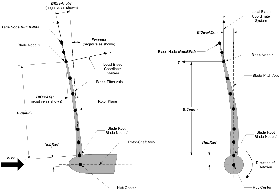
Fig. 6.3 AeroDyn Blade Geometry – Left: Side View; Right: Front View (Looking Downwind)